
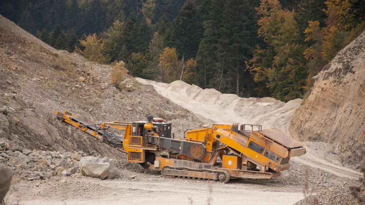
Mining equipment loads are heavy, motor-driven, and unforgiving. Operations that size generators incorrectly risk voltage drops, nuisance tripping, and costly equipment damage. Oversizing brings different penalties: high idle fuel consumption, wet stacking from incomplete combustion, and capital tied up in unused capacity. In remote mining camps, these costs multiply, because fuel and replacement parts are expensive to move.
This guide provides a direct, step-by-step method. Calculate running watts for every continuous load, add the largest starting surge, then apply a safety margin. Follow the sequence carefully, and the result is a generator matched to real demand, protecting both productivity and the equipment itself.
Inventory Mining Equipment Loads
The first step is a detailed load inventory. List every motor-driven asset on site. Record its running kW, starting kVA (locked rotor current), and power factor. This inventory becomes the foundation for every calculation that follows.
Record nameplate data
Nameplate data provides the raw numbers. Voltage, full load amps (FLA), power factor, horsepower, and locked rotor amps (LRA) each serve a specific purpose in generator sizing. Use FLA, not horsepower, as the electrical load for running-watt calculations. Horsepower identifies mechanical output only. Multiply LRA by voltage to estimate starting surge.
| Nameplate data | Use in generator sizing |
|---|---|
| Voltage (V) | Enter the motor’s rated voltage into running-watt calculations. |
| Full Load Amps (FLA) | Use FLA, not HP, as the electrical load for running-watt calculations. |
| Power Factor (PF) | Record if listed on the nameplate; used in the three-phase watt formula. |
| Horsepower (HP) | Identifies mechanical output only; do not use as electrical input. |
| Locked Rotor Amps (LRA) | Multiply LRA by voltage to estimate starting surge when sizing the generator. |
Some nameplates show only running amps. In that case, obtain locked rotor amps or manufacturer starting watt data from the equipment supplier. Missing data leads to guesswork, and guesswork leads to sizing errors.
Note simultaneous operation
Not every machine runs at once. Separate the load list into continuous and intermittent categories. Crushers, screens, conveyors, mills, ventilation fans, and dewatering pumps form the continuous base. Workshop tools, welding equipment, battery chargers, and drilling support equipment run intermittently.
Account for intermittent equipment through duty-cycle analysis and expected simultaneous load, not by adding full nameplate ratings to the continuous base. This approach prevents overcounting. A generator sized on connected kW alone will be far larger than necessary.
Load priority also matters. Ventilation, dewatering, and lighting are critical. Non-essential production equipment can be shed during an outage. This priority ranking keeps standby capacity from being overloaded by non-essential loads.

Calculate Running Watts for Continuous Duty
Running watts represent the steady electrical load the generator must supply hour after hour. Every motor that stays energized at full load during normal operation contributes to this total. These watts form the baseline for the entire sizing process. The generator must deliver this continuous load indefinitely while holding reserve for starting surges.
Convert amps and volts to watts
Voltage and current alone tell only part of the story. Power factor, the ratio of real power to apparent power, must enter every calculation. Induction motors draw reactive current that does no usable work. Ignoring this factor either overstates the load in watts or hides the true generator capacity required.
Single-phase equipment uses the formula watts = volts × amps × power factor. Three-phase motors, the standard in mining, use watts = volts × amps × power factor × 1.732. The constant 1.732 equals the square root of three, reflecting the phase relationship in three-phase systems.
Nameplate data supplies the input values. Use the motor’s rated voltage, full-load amps, and published power factor. When the nameplate omits power factor, request the value from the motor manufacturer. Do not substitute a generic estimate in the final sizing calculation.
Add continuous loads together
Sum the running watts for every load that operates during the same production cycle. Crushers, screens, conveyors, ventilation fans, and dewatering pumps normally form the continuous base. Leave standby and workshop equipment out of this total for now; that separation prevents overcounting.
Consider a three-phase crusher motor rated at 480 V, drawing 75 amps, with a 0.86 power factor. The calculation reads: 480 × 75 × 0.86 × 1.732 = 53,623 W, about 53.6 kW. Add a screen motor at 28 kW and a sump pump at 15 kW. The running-watt total reaches 96.6 kW. That figure becomes the baseline for the surge calculation covered next.
This total states the minimum sustained output the generator must manage. Only after adding the largest starting surge can the operator translate this number into a generator size.
How to Size Generators for Starting Surge
Motors draw a high inrush current at startup, often 3–7 times running amps. This brief spike lasts only seconds, but it determines whether the generator can start the largest load without collapsing voltage. The running-watt total from the previous step says nothing about this demand. Starting surge is the single most common reason operators size generators incorrectly.
Identify the largest motor surge
Find the single-highest starting watts figure among all motors on site. That motor, not the sum of all motors, drives the surge requirement. A 200 hp mill with a direct-online starter will demand far more inrush than a 50 hp conveyor, even when both run continuously. Identify the largest motor by horsepower and starting method, then obtain its starting watts from manufacturer data or locked rotor amps.
The locked-rotor code letter is a marking found on the motor nameplate. It places the machine in a band of locked-rotor kVA per horsepower, measured at full voltage and rated frequency. The letter is a ratio and a band, not a current or a single value, so it must be converted before it can be used to size protection or check supply capability.
Use locked rotor amps or starting kVA
When nameplate data lists locked rotor amps (LRA), multiply LRA by voltage to estimate starting surge. When only the code letter appears, convert it using the band table. For a 50 hp motor with code G at 460 V, the calculation reads: 6.3 × 50 = 315 kVA. Locked-rotor amps then equal 315,000 ÷ (1.732 × 460) ≈ 395 A. Conservative practice uses the top of the band for preliminary supply or starter checks.
| Letter | kVA per hp | Letter | kVA per hp |
|---|---|---|---|
| A | 0 – 3.15 | L | 9.0 – 10.0 |
| B | 3.15 – 3.55 | M | 10.0 – 11.2 |
| C | 3.55 – 4.0 | N | 11.2 – 12.5 |
| D | 4.0 – 4.5 | P | 12.5 – 14.0 |
| E | 4.5 – 5.0 | R | 14.0 – 16.0 |
| F | 5.0 – 5.6 | S | 16.0 – 18.0 |
| G | 5.6 – 6.3 | T | 18.0 – 20.0 |
| H | 6.3 – 7.1 | U | 20.0 – 22.4 |
| J | 7.1 – 8.0 | V | 22.4 and up |
| K | 8.0 – 9.0 |
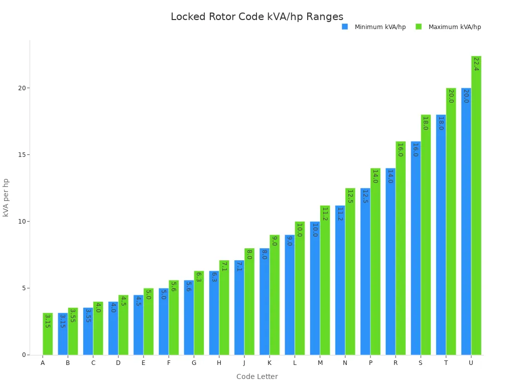
The code letter refers to specific machine conditions. For both 60 Hz and 50 Hz ratings, the letter refers to the 60 Hz figure. For Y start, delta run, it refers to the Y connection. For broad or dual voltage, it refers to the voltage giving the highest kVA per hp. For multispeed, it refers to the highest speed it can be started at, except constant-horsepower machines, which use the speed giving the highest kVA per hp. For part-winding start, it refers to the locked-rotor current for the full winding.
The 20/20 rule offers a guideline: size the generator so motor starting loads use no more than 20% of rated capacity. This rule is not a substitute for detailed calculations. It provides a quick sanity check, but the locked-rotor conversion remains the reliable method to size generators for surge conditions.
Combine Loads and Add a Safety Margin
Peak generator demand combines two numbers: the running watts of every load that operates at the same time, and the starting surge of the single largest motor. The largest motor already sits inside the running total, so its running watts must be removed before its starting surge is added. Here is the formula:
Peak kVA = (Total Running kVA – Running kVA of largest motor) + Starting kVA of largest motor
In words, the generator must handle the running loads of every other device plus the largest starting surge. Engineers who size generators for mining sites use this relationship first, because it yields the true momentary requirement.
Add largest surge to running watts
Only the largest starting surge belongs in the peak calculation. Other motors also draw inrush on startup, but their starts are staggered. Smart controls and programmable panels prevent two heavy motors from starting at exactly the same moment. When starts are spread out, the peak demand curve stays flat. One motor surge at a time is sufficient for the generator to manage. Sequencing is standard practice in motor control design.
A worked example shows the method. A mine reaches a 322.25 kW running total. The largest motor draws 48.8 kW at full load, and its starting surge is 292.8 kW. Subtract the motor’s running load from the total: 322.25 minus 48.8 equals 273.45 kW for all other equipment. Add the starting surge: 273.45 plus 292.8 equals 566.25 kW. That is the momentary capacity the generator must deliver when the largest motor starts.
Do not add every motor’s starting surge together. That overstates the peak load by assuming impossible timing. It also forces a generator far larger than the site needs, wasting fuel and capital.
Apply a 10–20% margin
The calculated peak load cannot stand alone. In mining, starts often occur under heavy mechanical load, so reserve capacity matters. A safety margin protects against voltage droop during starts, unexpected demand increases, and future load growth. Prime power generators at remote mining sites, which have no backup utility connection, need a larger cushion. Use 15-20% for those installations. Standby operation can tolerate 10-15%, though mining loads rarely fit that category.
A numerical example makes the margin clear. Start with a 1000 kW connected load. Apply a diversity factor of 0.85, reducing the value to 850 kW. Add 200 kW for motor starting, reaching 1050 kW. Apply a 15% safety margin: 1050 multiplied by 1.15 equals about 1208 kW. An engineer then specifies a 1350-1500 kW prime-rated generator. The larger unit holds voltage drop during motor starts to acceptable levels, around 15-20% maximum, so contactors do not drop out and motors do not stall. That same headroom supports future equipment additions.
Conservative design loads prime generators to 70-80% of rated capacity on average. That operating band leaves space for transient motor demand without sustained overload. Running above rated output for long periods shortens engine life and destabilizes voltage.
Do not rely on motor starting kVA alone to size generators. A broad starting kVA number ignores continuous running loads, which is why it produces either an undersized or oversized unit. The complete method — running watts plus the largest starting surge plus a safety margin — gives the only reliable answer. Every mining operation should run these numbers before renting or buying a generator.
Choose Generator Size and Avoid Oversizing
Match load to standard sizes
The calculated peak load rarely equals a standard generator rating. Match the number upward to the nearest available size. A generator sizing calculator can simplify this step. These tools divide total connected kW by power factor, add a safety margin, and return the required kVA. A mining camp drawing 1,050 kW at 0.85 power factor needs 1,235 kVA before altitude derating.
Understand oversizing risks
A generator larger than necessary brings real penalties. Wet stacking tops the list. This condition occurs when unburned fuel, carbon, and oil residues accumulate in the exhaust system. Diesel engines are designed to run at about 60–70% of rated capacity. Running below 30% load leads to incomplete combustion and fuel residue buildup. An oversized unit rarely reaches optimal load, so it stays too cool and becomes prone to wet stacking.
Fuel efficiency suffers as well. A lightly loaded engine burns more fuel per kilowatt-hour produced. Capital cost rises with every size increment. The engine load factor drops, which means the operator paid for capacity the site never uses. Proper load management, load bank testing, and right-sizing prevent these problems. The goal is a generator that runs in its efficient band, not one that sits idle at half capacity.
Proper generator sizing follows five steps. First, inventory every mining equipment load. Second, calculate running watts for continuous duty. Third, account for the largest motor starting surge. Fourth, combine loads and add a 10–20% safety margin. Fifth, select the nearest standard generator size.
Correct sizing prevents downtime, protects equipment, and controls fuel and maintenance costs. Before purchasing or renting, use the calculation method and manufacturer data. Do not guess.
When you size generators for mining operations, the process is manageable. Follow these steps, and the right unit becomes clear.