The most common mistakes in data center backup power design include undersizing generators, creating single points of failure, ignoring fuel supply logistics, neglecting battery maintenance, and failing to test regularly. These errors carry a heavy price. Recent industry research reveals the average cost of unplanned downtime has climbed to $9,000 per minute, or $540,000 per hour. This financial reality makes backup power reliability a critical business imperative. This article dissects each of these five errors. It explains their real-world consequences and provides actionable strategies to avoid them. Readers will gain clear expectations for building a more resilient power infrastructure.
Data Center Backup Power Design: The Cost of Undersizing
Undersizing remains one of the most expensive errors in data center backup power design. The problem typically begins with inaccurate initial load estimates. Engineers often calculate current demand without accounting for the relentless growth of IT equipment. A facility designed for today’s load may find itself critically short within three years. The financial consequences are severe. Research indicates that a single minute of downtime costs enterprises an average of $9,000, escalating into hundreds of thousands for prolonged outages. An undersized generator that fails during a utility failure transforms a manageable event into a catastrophic loss.
Consequences of an Overloaded Generator
When a generator operates beyond its rated capacity, the effects cascade through the entire electrical system. Undersized generators struggle to manage startup surges from motors, compressors, and HVAC systems. These temporary power spikes place excessive stress on both the generator and connected equipment. Over time, this leads to overheating, reduced equipment lifespan, and costly maintenance issues.
The operational instability manifests in measurable ways. Undersized generators cause voltage instability, frequency variations, and harmonic distortion. Insufficient capacity forces generators to operate at maximum output, creating voltage sags during load transitions. This directly compromises electrical efficiency by degrading power quality.
A ‘Dynamic Load Test’ reveals how voltage and frequency droop under load. The governor’s speed droop setting typically runs 4-5% for isochronous operation. Excessive droop indicates the generator cannot maintain rated speed. When frequency falls, the AVR’s V/Hz roll-off feature proportionally reduces output voltage. This protective mechanism prevents catastrophic failure but leaves sensitive equipment starved for power. Running appliances during low voltage damages motors and compressors. Sensitive electronics can suffer permanent damage from unstable voltage resulting from repeated overload conditions.
Calculating True Load for Future Growth
Proper load calculation requires a forward-looking approach. Bottom-up modeling builds electricity demand assumptions from individual component data, combining server power draw with facility efficiency and future equipment shipments. Top-down modeling combines geographic energy consumption estimates with demand for data center services. Both methods help operators avoid the pitfalls of reactive capacity planning.
| Aspect | Consequence of Undersizing | Correct Approach |
|---|---|---|
| Capacity Planning | Backup power insufficient after 3 years due to 40% IT load growth; must add generators or limit facility growth | Plan for 3-5 year growth; install 20-40% excess capacity initially; design for modular expansion |
| Financial Impact | Expensive generator additions, complex paralleling retrofits, lost revenue | Avoid retrofits with upfront scalable infrastructure investment |
A properly sized generator maintains stable voltage and frequency, protecting both the electrical system and the business it serves.
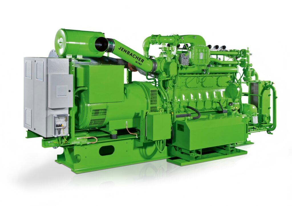
Single Points of Failure in Power Paths
A single automatic transfer switch (ATS) or one UPS module can silently compromise an entire backup power architecture. These components become single points of failure when designers assume redundancy exists without verifying the complete path from utility feed to server rack. Inadequate ATS design causes failures during power switching events. Loose connections and overloaded circuits further undermine redundancy. Physical infrastructure requires regular inspection to maintain true fault tolerance.
N+1 vs. 2N Redundancy Explained
Redundancy configurations determine how much fault tolerance a facility actually possesses. The choice between N+1 and 2N designs carries significant cost and reliability implications.
| Feature | N+1 Redundancy | 2N Redundancy |
|---|---|---|
| Definition | Adds one extra component to the required N components | Creates a fully mirrored, independent duplicate of the entire system |
| Number of components | N+1 (e.g., 5 UPS units if N=4) | 2N (e.g., 8 UPS units if N=4) |
| Cost | Lower, more energy efficient | Higher, less energy efficient |
| Fault tolerance | Minimal; risk of downtime if multiple simultaneous failures occur | Full fault tolerance; no single point of failure |
| Maintenance capability | Can service one component at a time | Can take an entire set offline for maintenance without interrupting operations |
N+1 configuration suits facilities with moderate uptime requirements. This approach provides one spare component for maintenance or failure. However, multiple simultaneous failures overwhelm the system. 2N architecture duplicates every component, creating complete isolation between power paths. This design allows full system maintenance without operational interruption. Data center backup power design decisions must weigh these trade-offs carefully against business continuity requirements.
Redundant Distribution and ATS Design
Automatic transfer switches require meticulous specification to avoid introducing new failure points. Proper ATS design follows several critical practices:
- Calculate total essential load and ensure ATS amperage rating meets or exceeds it.
- Verify generator compatibility: generator wattage must match or exceed load, and voltage/phase must match the ATS.
- Select appropriate NEMA enclosure protection (e.g., NEMA 3R or 4X for outdoor installations) based on environmental conditions.
- Use load management features to prioritize critical systems and prevent generator overload.
- Schedule regular visual inspections, functional tests, and annual professional maintenance.
Transition type selection also matters. Open transition suits most loads. Closed transition provides zero power interruption but requires utility coordination. Bypass-isolation ATS designs allow maintenance without downtime, making them essential for data centers. Compliance with NEC emergency circuit requirements and NFPA 110 standards ensures proper installation. Routine testing under load validates performance and integrates with emergency response planning. These practices transform a single ATS from a vulnerability into a reliable component of a resilient power path.
Fuel Supply and Logistics Oversights
Fuel storage capacity often receives insufficient attention during the design phase. Many facilities size their tanks for only 24-48 hours of operation. This approach proves dangerously inadequate during extended regional outages. Grid failures can persist for days or weeks. Natural disasters frequently disrupt fuel supply chains for extended periods. A data center without sufficient on-site fuel becomes vulnerable precisely when it needs protection most.
Fuel Storage Capacity and Refueling Contracts
The Uptime Institute establishes clear minimum standards for fuel storage. Their mandate requires at least 12 hours of on-site fuel for all Tier-defined data centers. This calculation assumes operation at full design load. The requirement supports the facility’s stated topology objective, whether Concurrently Maintainable or Fault Tolerant.
The Uptime Institute mandates a minimum of 12 hours of on-site fuel storage for all Tier-defined data centers. This requirement is calculated at ‘N’ load, meaning the fuel must support the facility’s full design load while running on engine generators, and must be sufficient to meet the facility’s stated topology objective (Concurrently Maintainable or Fault Tolerant).
Extended runtime capability provides critical operational continuity. On-site tanks enable generators to run during prolonged outages or grid instability. This capability supports uninterrupted performance for facilities maintaining network services and digital infrastructure.
Fuel logistics present additional challenges during emergencies. Transportation constraints create significant bottlenecks. Gravity-fed trucks carry 7,500 gallons but lack pumping capability. Pump trucks hold only 4,200 gallons, requiring double the deliveries. Facility design can worsen access problems. Enclosure-based generators surrounded by fences or transformers reduce truck access. These obstacles force long hoses and increase spill risk.
| Fuel Logistics Problem | Specific Detail |
|---|---|
| Reduced storage capacity | Diminishes operational flexibility during extended outages |
| Increased delivery frequency | More frequent deliveries raise supply chain disruption risks |
| Transportation constraints | Gravity-fed trucks (7,500 gal) lack pumping; pump trucks (4,200 gal) require double deliveries |
| Access issues | Enclosure-based generators reduce truck access, forcing long hoses and increasing spill risk |
Securing reliable refueling contracts requires proactive planning. Operators should follow a systematic approach:
- Contact suppliers to confirm their capability to deliver fuel and their outlook for future supply.
- Determine whether the supplier can sell fuel during a grid outage.
- Assess the need for additional on-site fuel storage based on supplier responses.
- Contract additional vendors for resupplies.
Pre-set agreements with fuel suppliers ensure prioritization during widespread outages. Operators should anticipate high demand and secure delivery assets in advance. Diversifying fuel sources mitigates risks from regional supply disruptions. Working with reputable distributors provides access to large networks and robust logistics.
Managing Fuel Quality and Contamination
Fuel degradation operates as a silent killer in backup power systems. Diesel fuel stored for long periods develops microbial growth, water contamination, and oxidation byproducts. These contaminants clog filters, corrode injectors, and degrade combustion efficiency. A generator with contaminated fuel fails precisely when called upon for emergency service.
The NFPA 110 Standard for Emergency and Standby Power Systems addresses this risk directly. It requires diesel generator fuel testing at least annually. Testing must use appropriate ASTM methods to verify fuel suitability for long-term storage.
| Testing Method | Description | Key Characteristics |
|---|---|---|
| CFU Testing | Cultures microbes from a fuel sample in an incubator | Detects all microbes; results take days; can mislead |
| ATP Testing | Measures light from ATP-mediated reaction indicating living microbial cells | Requires sterile conditions and specialist equipment; counts harmless microbes too |
| Immunoassay Antibody Testing | Targets microbes harmful to fuel using a test kit format | On-site results in minutes; complies with ASTM D6469 |
Regular fuel polishing removes contaminants and restores fuel quality. This process circulates fuel through filtration systems to eliminate water and particulates. Operators should implement scheduled testing and polishing programs. These practices ensure generators start reliably when utility power fails.
Battery Bank Health and Maintenance Gaps
UPS battery failure ranks among the most common electrical problems in data centers. The root cause is almost always neglected maintenance. Batteries degrade silently. Operators discover the problem only when the utility feed drops and the backup system cannot hold the load. Understanding the warning signs and implementing disciplined maintenance programs prevents this scenario.
Choosing the Right Battery Technology
The choice between VRLA and lithium-ion batteries shapes the entire maintenance strategy. VRLA batteries cost less upfront. They also require replacement every 3–5 years. Lithium-ion batteries carry a higher initial price—typically 1.5 to 2 times more—but they last 8–12 years. Over a 12-year window, the total cost of ownership for lithium-ion is lower because operators replace the bank once or not at all. VRLA requires roughly three replacements in that same period.
Physical characteristics also differ significantly. Lithium-ion batteries weigh 2–3 times less than VRLA units. They occupy 40–60% less floor space. This reduction matters in dense data center environments where square footage carries a premium.
Common signs of battery degradation include:
- Rising internal resistance or conductance drift, indicating aging or sulfation
- Dry-out and stratification, especially in VRLA with poor temperature control
- Terminal corrosion leading to localized heating and voltage imbalance
- Voltage imbalance across cells or strings
- Thermal anomalies detected via non-contact thermal imaging
Monitoring and Replacement Cycles
Monitoring capability separates the two technologies. VRLA batteries require periodic internal resistance checks of every jar. Technicians perform these checks two times per year when a monitoring system exists, or four times per year without one. Lithium-ion batteries include an integrated battery management system (BMS). This system provides continuous, real-time data on state of health and state of charge at the cell, module, and cabinet level. Operators gain a clear picture of runtime and health without manual intervention.
Industry standards from IEEE and NFPA recommend regular evaluation and proactive replacement. Predefined intervals typically fall between 3 and 5 years depending on chemistry and operating conditions. For VRLA, increased monitoring should begin at year three. Replacement planning should start at year four. Immediate replacement is recommended at year five regardless of apparent condition. Lithium-ion batteries should be replaced every 8–10 years or when capacity drops below 80%.
Data centers with battery monitoring systems experienced reduced outage rates from bad batteries compared to those without monitoring. UPS units receiving two preventive maintenance visits per year demonstrated 23 times better mean time between failures than units with no maintenance visits.
Continuous monitoring systems collect real-time voltage, temperature, and impedance data. Predictive analytics use trend analysis to schedule proactive maintenance. These systems integrate with Data Center Infrastructure Management platforms and provide cloud-based dashboards for multi-site visibility. Alarm protocols send SMS or email alerts when critical thresholds are crossed. This approach transforms battery maintenance from a reactive chore into a managed, data-driven process.
Inadequate Testing and Load Bank Validation
Why Annual Full-Load Testing is Critical
Routine no-load start-ups create a false sense of security. A generator that starts and idles smoothly may still fail when real power is needed. The NFPA 110 standard establishes a clear testing schedule: daily visual inspection, weekly no-load run, monthly one-third load test, and an annual full-load test. The annual test is the only way to uncover problems that only appear under stress.
The NFPA 110 (2025) protocol for the annual load bank test requires three stages. The generator must run at 50% of nameplate kW for 30 continuous minutes. It then runs at 75% of nameplate kW for 1 continuous hour. The total test duration must be at least 1.5 continuous hours. This sequence pushes the engine through its operating range and reveals hidden weaknesses.
Consider a real-world example. A 100 kW diesel standby unit had never missed a beat during routine start-ups. During a load test at just 50% load, the unit produced excessive black smoke. At 75% load, voltage dropped below specification. The root cause was clogged injectors and carbon buildup from years of light-load operation. No-load testing would never have caught this.
Diesel generators that run under light load for long periods suffer from wet stacking. Unburned fuel and carbon accumulate in the exhaust system. These deposits foul injectors, reduce combustion efficiency, and cause black smoke. Full-load testing brings the engine to proper operating temperature and burns off these deposits. Without this test, the generator may fail to ramp up to full power during a real outage. Facilities also face non-compliance with NFPA standards, resulting in penalties and increased liability.
Simulating Real-World Failure Scenarios
Validating the entire backup power chain requires more than a single successful transfer. Operators must simulate utility brownouts, single-phase failures, delayed generator starts, retransfer conditions, emergency stop events, and generator overload conditions. These scenarios mimic the variability of real outages.
Full-load transfer testing is essential. A no-load test is insufficient. Validation must include motor load restarts, voltage dips, harmonic increases, dynamic governor responses, and frequency recovery challenges. These conditions reveal hidden operational issues that a simple switchover cannot expose.
Pre-transfer verification steps ensure safe operation. All switching signals must be confirmed valid before initiating any transfer. Real-time load current must be within acceptable limits. Voltage sensing must be accurate within specified tolerances. Protective relaying schemes and coordination studies prevent cascading failures during exercise cycles.
An automatic transfer switch that has never been tested under full load may fail during an actual outage. Loose connections only show up when current flows. Voltage regulation problems only appear when the generator is loaded. By simulating real-world failure scenarios, operators validate every component in the power path from the generator to the server rack.
The five critical mistakes in data center backup power design—undersizing, single points of failure, fuel logistics oversights, battery neglect, and inadequate testing—are all preventable. Proper planning and diligence eliminate each vulnerability. These errors result from design choices and operational gaps.
Best Practices Checklist
- Right-size generators for current and future loads
- Eliminate single points of failure with N+1 or 2N design
- Secure long-term fuel contracts and monitor fuel quality
- Implement a battery maintenance schedule with regular testing
- Conduct full-load tests at least annually
Data center backup power design is not a static installation. It requires continuous investment and attention. Operators who treat it as such ensure long-term reliability and business continuity.