Your generator starts, but can it handle the surge when the cooling system kicks in? Load acceptance measures a generator’s ability to manage sudden load increases. These increases cause voltage or frequency deviations. Such deviations disrupt IT equipment. A generator that starts is not the same as one that can accept the load. This distinction is vital for data center uptime. Therefore, operators must evaluate generator load acceptance through proper testing. The evaluation process includes analyzing the load profile, conducting step load tests, and comparing results against industry standards. Understanding these steps protects against costly failures.
How to Evaluate Generator Load Acceptance Fundamentals
Defining Load Acceptance vs. Generator Sizing
Generator sizing determines the total capacity needed to support the steady-state load. It ensures the unit can supply enough power for all connected equipment. Load acceptance, however, focuses on transient response. The generator must handle sudden load increases without causing voltage or frequency deviations that disrupt IT equipment. This distinction is critical for data center operators. To properly evaluate generator load acceptance, one must understand that a generator rated for the full load may still fail if it cannot accept a large step load quickly.
ISO 8528-5 defines transient response standards for generator sets. For data centers, the required performance class is G3. This class imposes strict limits on voltage and frequency stability during transient events. The table below summarizes the key G3 compliance criteria:
| Technical Requirement | G3 Compliance Criterion |
|---|---|
| Voltage Regulation | ±1% of rated value during stable operation |
| Frequency Regulation | ±0.25% at steady state |
| Transient Response | Recovery within strict limits after load changes |
| Harmonic Distortion | Total harmonic distortion (THD) within acceptable limits |
| Load Acceptance | Must accept large load steps without significant voltage/frequency drop |
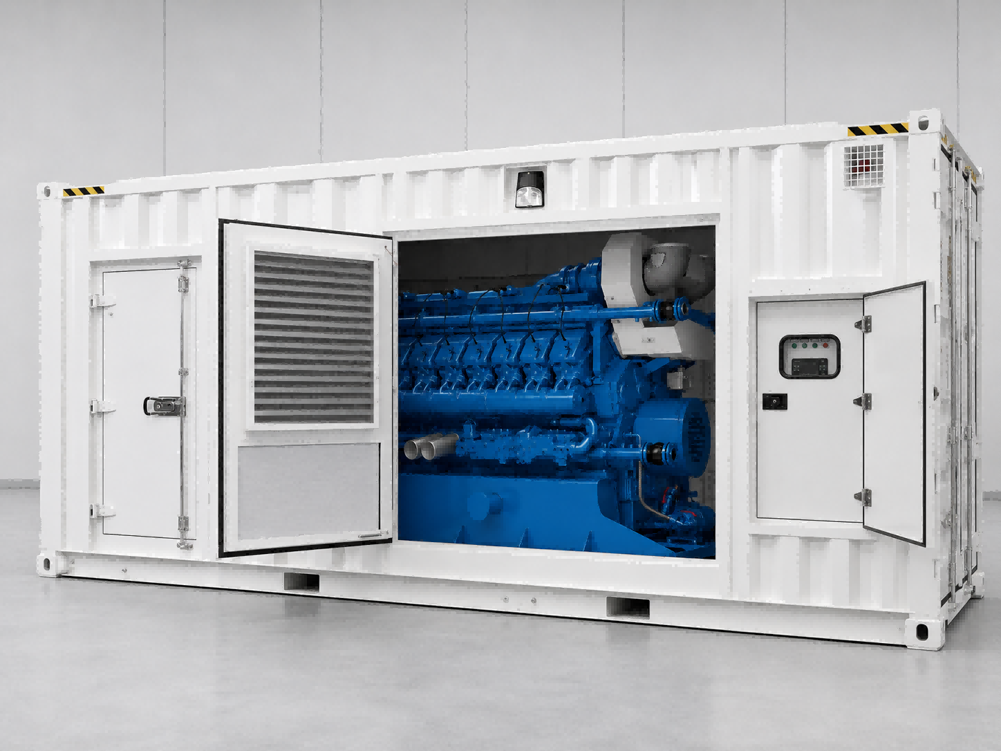
The SWT SME Series (1800kW/2250kVA) is designed for rapid load pickup. Its robust alternator and advanced controller support quick response to sudden load changes. However, testing remains essential to verify performance in a specific data center environment. Each facility has unique load characteristics that affect transient behavior.
Key Metrics: Voltage Dip and Frequency Response
Voltage dip and frequency response are the two primary metrics for evaluating load acceptance. Voltage dip occurs when a large load step causes a temporary drop in voltage. Frequency response measures how quickly the generator recovers its rated speed after a load change. Both must stay within acceptable limits to protect IT equipment.
Cooling systems are a common source of transient loads in data centers. An air conditioner might pull 10 amps while running, but it could pull 50 amps for a split second when the compressor starts. This indicates a 5x inrush factor (50/10) for a cooling system motor, which is the type of transient spike that must be accounted for in generator sizing to prevent voltage drops.
ISO 8528-5 sets specific limits for frequency deviation during step load tests. The table below shows the maximum allowable transient frequency deviation for G2 and G3 classes:
| ISO 8528-5 Performance Class | Maximum Allowable Transient Frequency Deviation (Step Load) |
|---|---|
| Class G2 | ≤ -10% |
| Class G3 | ≤ -7% |
G3 compliance requires tighter control. The generator must return to steady-state frequency within a few seconds after a load step. Voltage dip limits are also strictly regulated, though the exact value depends on the load type. For data centers, staying within ±1% voltage regulation at steady state and ensuring rapid recovery after transients is essential for reliable operation.
Step-by-Step Load Acceptance Testing Process
Analyzing the Data Center Load Profile
A thorough load profile analysis forms the foundation of any successful testing program. Data center operators must examine both steady-state and transient loads. Steady-state loads include IT equipment that draws consistent power during normal operation. Transient loads are more challenging. They include inrush currents from cooling system compressors and UPS charging circuits. A cooling system motor might draw five times its running current for a fraction of a second during startup. This surge can cause a significant voltage dip if the generator cannot respond quickly enough.
The SWT SME Series (1800kW/2250kVA) is designed to handle these rapid load changes. Its advanced alternator and controller provide fast voltage and frequency recovery. However, every data center has a unique load profile. The specific combination of IT loads, cooling systems, and UPS equipment determines the actual transient demand. Non-linear loads from modern IT equipment also create harmonic distortion. This distortion can affect generator stability if the automatic voltage regulator cannot compensate. Operators must document all these load characteristics before testing. This documentation helps them set realistic test parameters and avoid unexpected failures during a real power event.
A complete load profile analysis should include the maximum expected step load size. It should also identify the sequence of load applications. For example, a data center might apply cooling loads first, followed by UPS charging and IT equipment. Understanding this sequence allows operators to simulate real-world conditions accurately during testing. The analysis should also account for load growth over time. As data centers add more servers and storage, the transient demand increases. Regular updates to the load profile keep testing relevant. To properly evaluate generator load acceptance, operators must first understand the full range of loads the generator will face.
Conducting Load Bank and Step Load Tests
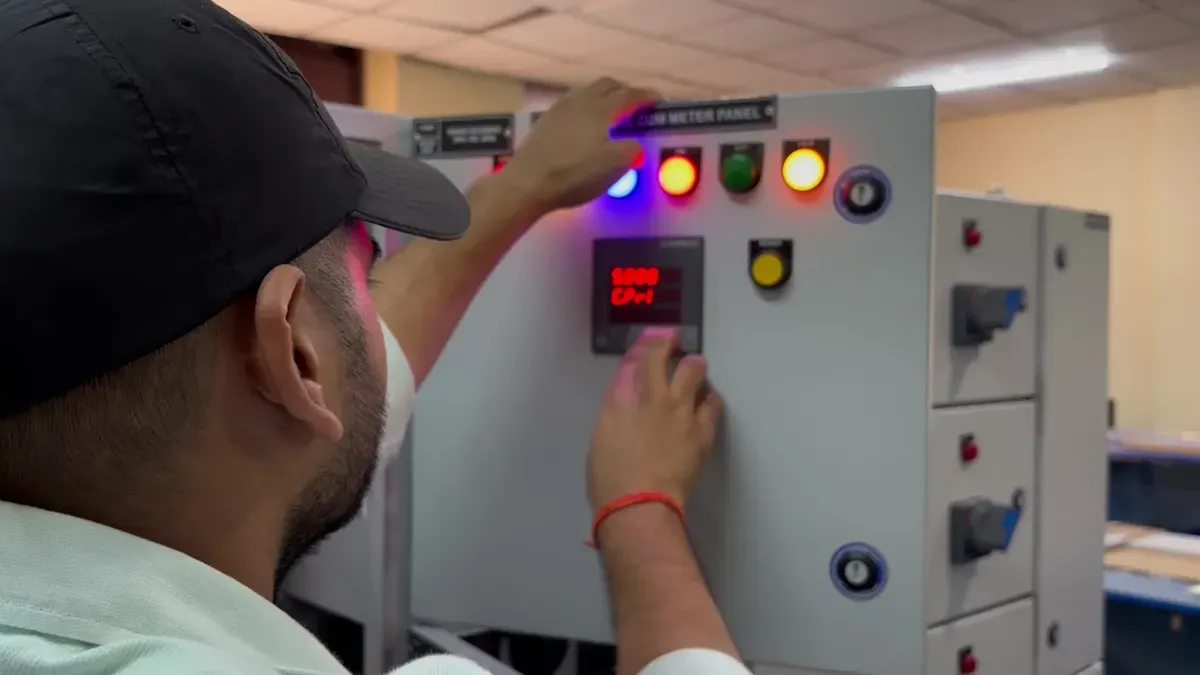
Load bank testing verifies that the generator can handle the loads identified in the profile analysis. NFPA 110 provides clear requirements for emergency power supply systems in data centers. Monthly testing is essential. The generator must run at a minimum of 30% of its nameplate rating for at least 30 continuous minutes. This practice prevents wet stacking and ensures operational readiness.
| Test | Frequency | Load Requirement | Duration |
|---|---|---|---|
| Monthly exercise | Every 30 days | ≥30% of standby nameplate kW | 30 continuous minutes |
| Annual supplemental load bank test | Annually, only if monthly test fails to reach 30% threshold | 50% then 75% of nameplate kW | 30 min at 50% + 1 hr at 75% |
| Triennial run | Every 36 months (Level 1 systems) | ≥30% of nameplate kW | Class duration or 4 hours, whichever is less |
If the monthly exercise does not achieve the 30% load threshold, an annual load bank test is required. This test applies 100% of the rated load for a minimum of two hours. For routine verification, a full load step can be held for 30 minutes, excluding warm-up and cool-down periods.
Step load tests are the most direct way to evaluate generator load acceptance. These tests apply sudden load increases that simulate real-world events. Single-step tests add a large load block all at once. Multi-step tests apply loads in stages, matching the sequence of actual equipment startup. The generator must maintain voltage and frequency within acceptable limits during each step. Operators should measure voltage dip and frequency deviation with precision instruments. Recovery time is also critical. The generator should return to steady-state operation within seconds after each load step.
The SWT SME Series performs well under these conditions. Its robust design supports rapid load pickup without excessive voltage dip or frequency deviation. The generator meets ISO 8528-5 G3 requirements for transient response. Operators should document all test results carefully. This documentation provides evidence of compliance with NFPA 110 and ISO 8528-5 standards. It also helps operators identify any degradation in generator performance over time. A gradual increase in recovery time may indicate wear in the governor or voltage regulator.
Regular testing builds confidence in the backup power system. A generator that passes step load tests under controlled conditions is more likely to perform during a real emergency. Data center operators who follow these procedures can protect their critical loads and maintain uptime. The combination of load profile analysis and rigorous testing creates a complete picture of generator readiness. These procedures provide a reliable method to evaluate generator load acceptance in any data center environment.
Interpreting Test Results and Acceptance Criteria
Once load bank and step load tests are complete, the data must be interpreted. Operators compare measured voltage dip, frequency deviation, and recovery time against established limits. These limits come from industry standards like ISO 8528-5 and the ITIC (CBEMA) curve. Understanding these criteria determines if the generator can protect sensitive IT equipment. Without proper interpretation, test results have no meaning. A generator that starts but fails to meet these criteria may still cause downtime during a real power event.
Setting Pass/Fail Thresholds for Power Quality
ISO 8528-5 defines acceptable limits for generator sets. For most data center applications, voltage dip should not exceed 20% of nominal during a load step. Frequency dip should not exceed 10% of nominal. These limits ensure transient events do not disrupt equipment. Exceeding these limits can cause IT equipment to reset or fail.
The ITIC (CBEMA) curve provides voltage tolerance guidance. This curve specifies what voltage levels equipment can withstand. The table below shows the key limits:
| Event Type | Voltage Tolerance Limit | Maximum Duration |
|---|---|---|
| Steady-state | ±10% of nominal | Continuous |
| Voltage swell | 120% of nominal | 0.5 seconds |
| Voltage sag (shallow) | 80% of nominal | 10 seconds (600 cycles) |
| Voltage sag (deep) | 70% of nominal | 0.5 seconds (30 cycles) |
| Dropout / interruption | <70% of nominal or complete loss | 20 milliseconds (1.2 cycles) |
These limits set pass/fail thresholds. If the generator causes a voltage sag below 80% of nominal for more than 10 seconds, the test fails. A voltage swell above 120% of nominal for more than 0.5 seconds causes failure. The generator must maintain voltage within ±10% of nominal during steady-state operation. Any deviation beyond this range indicates a problem with the automatic voltage regulator. The regulator may need adjustment or replacement. Operators should not ignore these deviations. They can cause cumulative damage to IT equipment over time.
Analyzing Transient Behavior and Recovery Time
Recovery time is equally important. After a load step, the generator must return to stable operation quickly. The frequency must recover to within 1% of nominal speed. ISO 8528-5 G3 compliance requires this recovery within 5 seconds.
Frequency recovery to ±1% ≤ 5 s (ISO 8528-5 G3)
This requirement means the generator must stabilize frequency within 5 seconds after a sudden load change. A slower recovery time indicates a problem with the governor or fuel system. The generator may not handle real-world transients in a data center. Operators should investigate any recovery time that exceeds 5 seconds.
Operators should measure both voltage and frequency recovery times during each step load test. Single-step and multi-step tests both provide valuable data. The recovery time should decrease as the generator warms up. A consistently long recovery time suggests maintenance is needed. The SWT SME Series (1800kW/2250kVA) is designed to meet these requirements. Its advanced governor and voltage regulator provide fast response. However, each installation has unique characteristics. Field testing remains essential to verify performance in a specific environment.
Documenting all test results is critical for compliance. Operators should keep a testing log. The log should include voltage dip, frequency deviation, and recovery time for each load step. This log provides evidence of compliance with NFPA 110 and ISO 8528-5. It also helps operators track performance trends. A gradual increase in recovery time may indicate wear in components. Early detection allows operators to schedule maintenance before a failure occurs. This proactive approach reduces downtime risk and extends generator life.
To evaluate generator load acceptance effectively, operators must combine test data with these criteria. The criteria provide a clear benchmark for success. A generator that passes these tests can handle sudden load changes. A generator that fails requires immediate attention. The root cause could be a faulty governor, a weak voltage regulator, or improper fuel delivery. Testing under different load conditions reveals the generator’s true capabilities. Operators should consult the manufacturer for guidance on corrective actions. Regular testing ensures the generator remains ready for any power event. The combination of proper testing and correct interpretation protects data center uptime.
Common Pitfalls and Best Practices for Load Acceptance
Managing Non-Linear Loads and Inrush Current
Modern IT equipment draws non-linear loads. These loads create harmonic distortion in the generator’s voltage output. Excessive distortion causes overheating and instability. The automatic voltage regulator must compensate for these harmonics. Without proper compensation, the generator may become unstable.
The table below shows typical acceptable voltage THD limits for different load categories:
| Load Category | Typical Acceptable Voltage THD Limit |
|---|---|
| UPS Systems and Admin building loads | 10% |
| Inverter Drives (VSD) and industrial equipment | 15% |
| Soft Start Systems (short-term, bypassed) | 20% |
| Diode-based rectifier systems only | 20% |
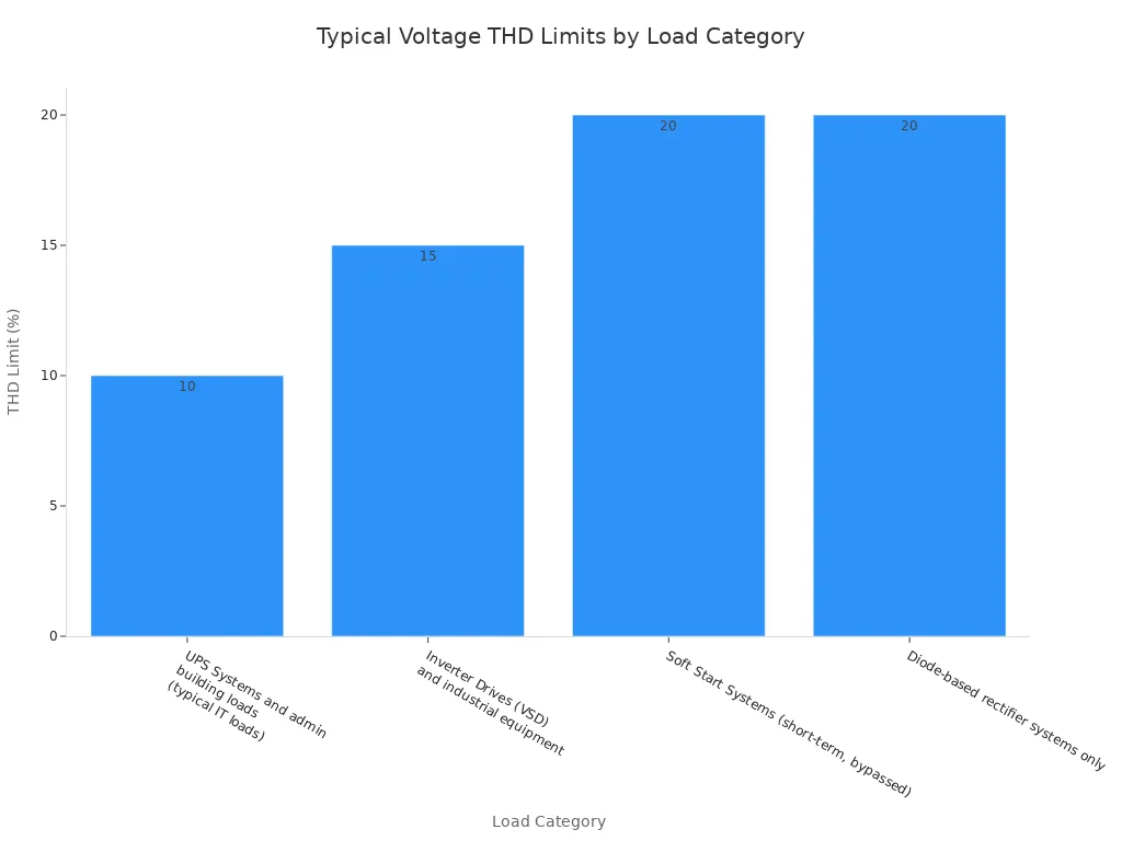
Data centers with UPS systems must keep THD at or below 10%. Exceeding this limit can cause premature equipment failure. The SWT SME Series alternator handles these harmonics effectively. However, operators should verify performance through testing.
Inrush current from cooling systems creates another challenge. A compressor motor may draw five times its running current during startup. This surge stresses the generator’s voltage regulator. The generator must respond quickly to prevent voltage dips.
Common failure causes during load acceptance tests include:
- Fuel system problems: contaminated fuel, clogged filters, blocked fuel supply
- Battery and starting system issues: battery degradation, charger faults
- Cooling failures: coolant leaks, blocked radiators, overheating
- Electrical faults: failing sensors, control board issues
- Neglected maintenance: small issues escalating over time
Best Practices for Testing and Documentation
Regular testing prevents most of these failures. Monthly load bank testing at minimum 30% load keeps the generator ready. Annual testing at 100% load verifies full capacity. Operators should test under various load scenarios. Single-step and multi-step tests reveal different performance characteristics.
NFPA 110 requires specific documentation. The test log must include:
- Output voltage measured on all three phases (within ±5% of rated)
- Output frequency at 60 Hz ±0.5 Hz under load
- Load on generator measured and compared to rated capacity
- Engine coolant temperature monitored and logged
- Engine oil pressure logged
- Exhaust smoke colour observed
- Fuel consumption compared to baseline
A complete test log helps operators track performance trends. Gradual changes in recovery time indicate wear. Early detection allows preventive maintenance. Operators should coordinate with the generator manufacturer for support. SWT provides validation and guidance for the SME Series. This partnership ensures the generator meets ISO 8528-5 G3 requirements.
To evaluate generator load acceptance properly, operators must combine rigorous testing with thorough documentation. This approach protects uptime and prevents costly failures. Regular evaluation ensures the generator remains ready for any power event.
Evaluating generator load acceptance requires a systematic approach. Operators must understand transient response fundamentals, analyze the complete load profile, conduct load bank and step load tests, and compare results against ISO 8528-5 criteria. Each step builds confidence in the backup power system.
Load acceptance is not a one-time event. Monthly testing at minimum 30% load keeps the generator ready for real emergencies. Annual full-load tests verify complete capacity. This ongoing process identifies performance degradation before failures occur.
A thorough evaluation protects uptime and prevents costly downtime. Regular testing reveals developing issues early. Operators who follow these procedures ensure their data centers remain operational during any power event. Regularly evaluate your generator’s load acceptance to ensure your data center is truly prepared for any power event.